elibaum.com
Reverse engineering a Twine environment sensor
08 Aug 2022
August 2022: after a long hiatus, I am finally posting this online. The following work was performed in 2021 during COVID lockdown, right before I started a new job at MITRE. Lucky for me, my projects at MITRE ended up being very similar to this project, so I didn’t really return to it. I still want to post my notes, however, for posterity.
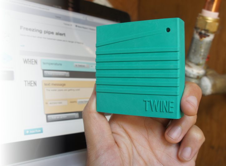 The Twine Sensor. Image credit supermechanical.com
I had an old Twine environment sensor lying around. It’s a discontinued product from Supermechanical that measures temperature, vibration, and (with optional external boards) various other environmental parameters. It connects over WiFi and can run very simple scripts. (If the temperature exceeds 95°F, send me an email; turn on the light when Twine is flipped upside down.)
As it stood, Twine was pretty much useless to me, but I figured the WiFi-enabled sensor platform could be a promising launchpad for building other IoT-esque systems.
Unfortunately, Twine was not very extensible (unless I built a custom sensor to plug into the external sensor port). Even so, I didn’t love the extremely limited cloud functionality, and there wasn’t an API available to build custom software.
I decided it would be good practice to try to reverse engineer Twine, both to learn how it worked, and possibly find a way to bend its functionality to something a bit more useful. I envisioned a few angles of attack:
- What does the internet traffic look like?
- Can I get anything from the USB port? Directly off the hardware itself?
- If I can get my hands on it, is there anything interesting in the firmware? Possible vulnerabilities?
This is a largely incomplete investigation – I started a new job, and (shocker) having a real job takes a lot of time!
- Twine Basics
- Hardware Overview
- Network
- Firmware Analysis
- USB Port
- Flash Memory Dump
- to be continued?
Twine Basics
After connecting to your Wifi network, Twine can be controlled via a simple online interface. Power comes from a USB cable or 2xAA batteries.
Here’s what some rules could look like:
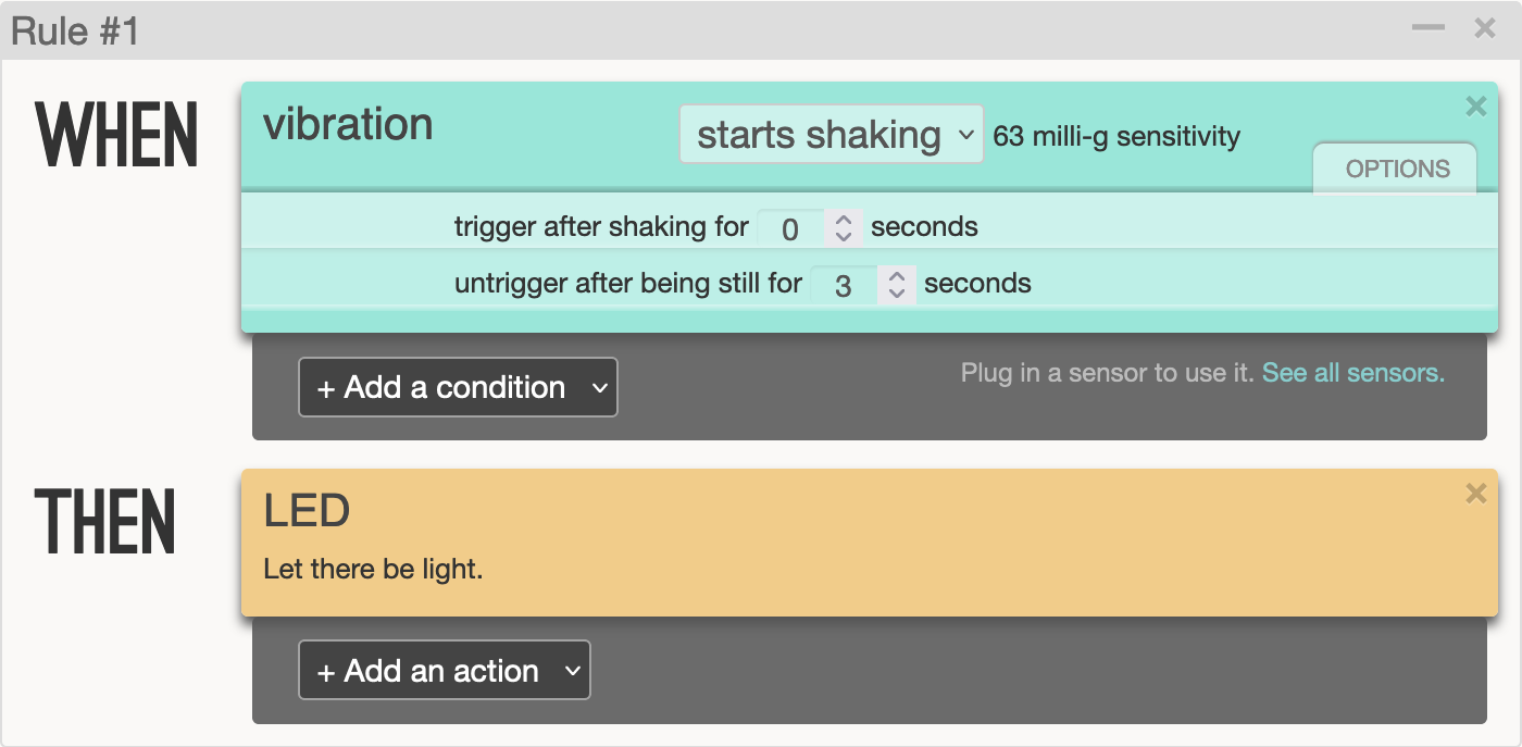
Rule #1 turns on the LED when Twine registers a fixed amount of vibration (configurable in the settings), and turns the LED off once the vibration stops.
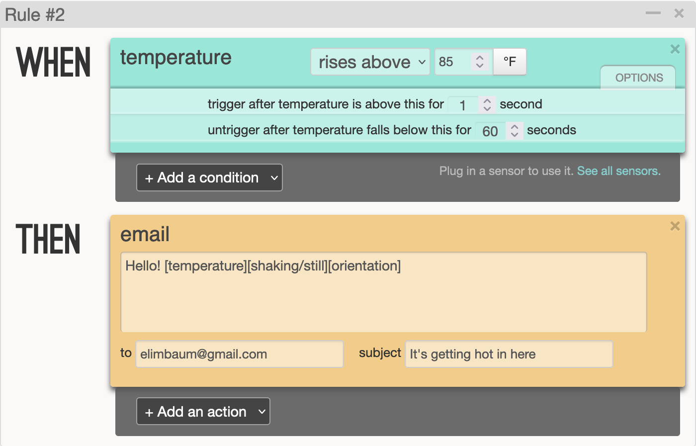
Rule #2 sends me an email when it warms up to above 85°F.
Unfortunately, you can only register one rule per sensor - there’s no way to have one action when the temperature rises above a threshold, and a different action when the temperature drops below a different level. You can add multiple actions, however. Available actions are:
- Turn on the LED
- Send an email or SMS
- Tweet (!)
- Place a phone call and speak some text
- Send an HTTP POST or GET request
The actions are admittedly pretty useful; I just found it frustrating that there was no way to create more complex sensing procedures without, say, building a HTTP backend to handle further logic.
So, time to dig in.
Hardware Overview
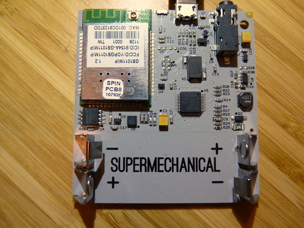
There are three main ICs of interest here:
STM32F100C832-bit ARM microcontrollerGS1011MIPWiFi Module (formerly Gainspan, now Telit)- This module contains both a wireless processor and an user-programmable general purpose processor. Perhaps they’re using it as a controller for the ARM? Or vice versa?
W25Q80BV8Mbit SPI flash memory
There’s also a USB connector for power(?), a 3.5mm audio jack for external sensors, and some other random circuitry.
Presumably the STM32 microcontroller runs the show, the GS1011 provides network connectivity, and either data or firmware are stored in the flash.
Network
I took a look at the internet traffic first. Since Twine connects over WiFi, I set up internet forwarding on my Mac, connected Twine to an old Airport Express, and routed the internet connection over ethernet to my Mac. This allowed me to run a packet capture on the ethernet interface to see Twine’s traffic.

Couple of things off the bat:
-
Twine connects to an AWS server at
f-router1.0.supermechanical.net, on ports32887(UDP) and32888(TCP). No other IPs (besides DNS) are accessed. -
UDP packets are always about 340 bytes, and only from Twine to server (with no response). There’s some cleartext (“udp” and “data”), but seems likely to be encrypted based on entropy. I suspect this is the actual data.
-
TCP packets look like command and control – seeing text like “poll”, “rssi”, and “wakeup”. These packets are going in both directions, but often the responses from the server just contain a bunch of null bytes.
-
Twine is very slow to respond to pings. I don’t have enough insight into the WiFi-layer traffic to know if this is strictly true, but I suspect that (except in fast mode) Twine turns off the WiFi chip between transmissions to save power (so it will rarely accept incoming messages).
- Future work: run a Wifi dongle in monitor mode and sniff the actual 802.11 traffic. May even be able to do this by setting up my laptop has a base station and running a pcap on the radio interface.
nmapdoesn’t report anything.
Each packet sent over the network seems to have a similar structure. UDP data packets are encrypted, but the header is in the clear. TCP packets are never encrypted.
I ran a long packet capture and started comparing different types of messages:
Data packets
All data packets start like this (removing unprintable characters):
..u.ñl.....B............udp..0............data..!...
Full hex dump:
00000000  00 00 75 c2 92 c3 b1 6c 0f 7f 03 00 05 42 01 00  |..u....l.....B..|
00000010  00 02 00 00 00 04 04 00 00 00 75 64 70 00 06 30  |..........udp..0|
00000020  01 00 00 02 00 00 00 04 05 00 00 00 64 61 74 61  |............data|
00000030  00 04 21 01 00 00                                |..!...|
This kind of looks like there’s some kind of length-value format. For example, a few bytes before the string udp\0 we see 0x4; before the string data\0 we see 0x5. Maybe the 0x4 before each of those is the length of the length?
I’m imagining something like this:
04 05 00 00 00 00 64 61 74 61 00
\  \              \____ 5 bytes = "data\0"
 \  \____________ length
  \_ length of length
Right after that, we see 04 21 01 00 00, which would seem to imply a following chunk of size 0x121 or 289 bytes. That seems about right… the UDP packets were always around 340 bytes (including this 54-byte header).
After the header, we get encrypted data. I wasn’t able to discover anything here. (Later, by looking into the firmware, I learned they were likely using the XTEA cipher, but was unable to find the key.)
Control Messages
These messages are not so consistent. I’ve highlighted where differences occurred with a hash mark #.
Poll
These are sent occasionally - when Twine flips over, and also on some timer. I’m assuming this is how Twine checks for updates from the server.
..u.ñl..#..K............poll..8........ÿ....gsversion......Nov 17 2012-13:47:11......rssi..#...
First difference is some counter, maybe a sequence number? Second is RSSI. The gsversion field is, I assume, the Gainspan firmware version, since Nov 2012 was before Twine even existed.
Hex dump:
00000000  00 00 75 92 f1 6c 0f 7f 01 00 05 4b 00 00 00 02  |..u..l.....K....|
00000010  00 00 00 04 05 00 00 00 70 6f 6c 6c 00 06 38 00  |........poll..8.|
00000020  00 00 04 00 00 00 04 ff 00 00 00 00 67 73 76 65  |............gsve|
00000030  72 73 69 6f 6e 00 04 15 00 00 00 4e 6f 76 20 31  |rsion......Nov 1|
00000040  37 20 32 30 31 32 2d 31 33 3a 34 37 3a 31 31 00  |7 2012-13:47:11.|
00000050  04 05 00 00 00 72 73 73 69 00 02 dd 00 00 00 0a  |.....rssi.......|
Again, seeing the LV format here.
Network Status
This message never changed. Twine sends when first connecting to a WiFi network (including when reassociating after being woken up from sleep.)
00000000  00 00 75 92 f1 6c 0f 7f 00 00 05 14 00 00 00 02  |..u..l..........|
00000010  00 00 00 04 06 00 00 00 6e 77 5f 75 70 00 06 00  |........nw_up...|
00000020  00 00 00 00 00 00 00 0a                          |........|
Wakeup message
Sent from server to twine over TCP. Always the same:
00000000  00 00 00 00 00 00 00 00 00 00 05 15 00 00 00 02  |................|
00000010  00 00 00 04 07 00 00 00 77 61 6b 65 75 70 00 06  |........wakeup..|
00000020  00 00 00 00 00 00 00 00 0a                       |.........|
Null messages
Server response to poll when no updates are available.
........#..ÿ.............null.
Sometimes that byte is 0x00, and sometimes it is 0x01. Huh.
Example hex dump:
00000000  00 00 00 00 00 00 00 00 01 00 05 ff 00 00 00 00  |................|
00000010  01 00 00 00 04 05 00 00 00 6e 75 6c 6c 00 0a     |.........null..|
These are the messages we see in normal operation. But when updating a rule on the Twine website, we see a ton of activity. I’m not doing to go through the whole PCAP, because it’s a lot, but basically the server replies to a poll request with an arm_flash message. Then, after a bit of a handshake, the Twine downloads a binary blob, 256 or so bytes at a time.
Naturally, I got suspicious - this looks an awful lot like we are reprogramming the ARM! Is this just straight (encrypted, unauthenticated) machine code?
Well, yup! After some headscratching, I managed to extract the full blob and load it into Ghidra. Time for reverse engineering!
Major annoyance here: for some reason, the byte
0x0ais never sent. This may be related to the fact that all UDP packets appear to end with0x0a. I eventually realized that0x0abytes were being encoded as0xff00; accordingly,0xffwas encoded as0xff01.Incidentally, this is why packet sizes weren’t uniform: if a given packet included many
0x0aor0xffbytes, its size on the wire would increase. I observed packets 10-20 bytes larger at times.Anyway, I have no idea why they did this. Presumably
0xais their end-of-packet marker. But UDP already gives you a length! Buffer overflow protection from a malicious server, maybe?
Anyway, time for some analysis!
Firmware Analysis
This was one of my first times using Ghidra, but it was a great project to learn on: ARM isn’t too terrible, and Ghidra support for the chip at play here (Cortex-M3) is quite good. Also, there were a lot of strings in the code.
I ended up not finding a ton of usable, interesting things within the firmware, but the very fact that this firmware is transmitted over an unencrypted UDP connection is a major issue, because it means I could trivially rewrite the ARM firmware on the Twine! (There was no integrity protection except for a CRC.)
High level steps here:
- Spoof a WiFi base station with matching SSID. Since Twine fully disassociates from the network, it shouldn’t be too tricky to run a false base station.
- Spoof a DNS server to give a malicious IP for
f-router1.0.supermechanical.net. - Trigger a poll on the Twine (periodically, by flipping it upside down, or maybe by sending a
wakeupcommand), which will be routed to our malicious server. - Reply with new, custom firmware!
This basically accomplishes what I would have wanted to do for custom sensing applications. It doesn’t accomplish full flexibility because I haven’t figured out how to modify (or even view) the Gainspan firmware.
Message Passing
The biggest clue to the separation of functionality between the ARM chip and Gainspan was the message passing code I discovered.
The function at 0x08006038, which I called build_msg_for_server, was always called when it was time to send a message, accompanied by a particular kind of format string. A good example of this comes around address 0x800966c:
build_msg_for_server(
	"[s{sss[[ns][ni][ns][ni][ni][ni][ni][ni]]}]",
	auStack600, "update", "ruleset_id", DAT_2000009c, "values", 1,
	PTR_DAT_0800968c, "2.02", 1, &DAT_20000088, local_2c, 1, &DAT_20000089,
	*(undefined4 *)(&DAT_20000070 + (uint)*(byte *)(param_1 + 8) * 4), 1,
	&DAT_200000a0, &local_3c, 1, &DAT_200000a1, &local_40, 1, &DAT_200000a2,
	&local_44, 1, &DAT_2000008a, &local_34, 1, &DAT_200000a3, &local_38);
Lot of useless decompilation artifacts there that I don’t understand. But this weird "[s{sss[[ns][ni]..." format string comes up a bunch. I suspect this is a simple type encoding – s for string, i for integer, maybe n for length? That could explain all of the 1s that we see in the argument list.
Here are some other format strings:
[s{}]
[s{ss}]
[s{sn}]
[s{sssssssss[[ni][ns][ni][ni]]}]
[s{sssssssss[[ni][ns][ni]]}]
[s{sss[[ns][ni][ns][ni][ni][ni][ni][ni][ni]]}]
[s{sss[[ns][ni][ns][ni][ni][ni][ni][ni]]}]
The brackets always appear to match, but I’m not quite sure what the semantics are.
I also sometimes observed my email appearing, in plain text, in the arguments to the build_msg_for_server function, when I created a rule with an email action.
Once generated, these messages are forwarded over UART to the Gainspan.
So I’m thinking these are some kind of formatted command string being sent to the Gainspan – which then either sends an email, or routes data to the main server. (This could be a way to generate custom messaging, if I figured out the format string.)
Encryption
The messages on the wire were clearly encrypted, so while I was looking at the message-sending flow, I was also keeping an eye out for possible encryption.
After every call to build_msg_for_server, another function at 0x08003b60, which I called send_message, appears to handle the actual communications. But this function also is the one providing encryption!
A pseudo-C excerpt:
send_message(message_buffer, message_len, param_3, should_use_tcp)
{
  ...

  uVar1 = mb_xtea_block_cipher(message_len,message_buffer);

  if (should_use_tcp)
	esc_str_len = build_msg_for_server(
		"[s{sn}]", PTR_DAT_08003d14, "tcp", "data",uVar1, message_buffer);
  else
	// udp case similar
...
}
So, we pass a plaintext message in, encrypt it in place, and then re-encode that binary blob with another format string. This is what actually is sent over the wire – recall that we saw outbound messages with strings udp and data followed by encrypted blobs, and using TLV encoding.
I didn’t know XTEA was being used at the time, but after staring at the function for a while and cross-referencing against common encryption functions (particularly using the magic constants), I was able to identify a match.
Here’s a bit of the decompilation:
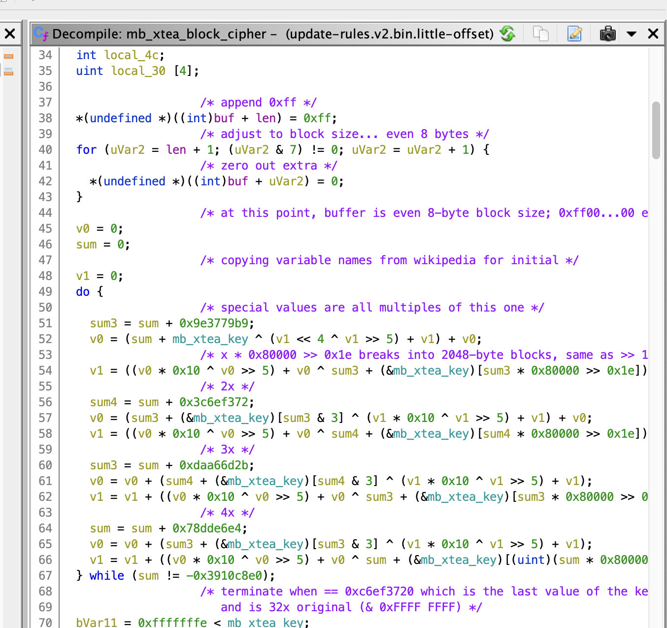
Referencing the Wikipedia article about XTEA and this C++ implementation I feel relatively confident I’m looking at XTEA.
The next natural question is – what’s the key? By comparing my code to published implementations, I was able to identify the variable that likely held the key. Tracking this back, we end up at an SRAM location – one which is never written to! (That’s at 0x20000008c.)
My best guess at this point is that when the ARM chip is flashed by the Gainspan, the key is loaded into SRAM.
(It would be natural to assume that the keys are stored in the external SPI flash memory. However, that chip seems to be connected to the Gainspan, not the ARM; and, as we will see below, it doesn’t look like that chip is holding keys.)
USB Port
As I was working on the network captures, I also thought a bit about the USB port. Much of what I learned from this investigation confirmed what I suspected from what I was seeing over the network; I probably would have saved myself a lot of time and guessing had I looked at this first.
Twine gets power from a micro USB port, but it doesn’t register as a USB device when I plug it into my computer. I checked the resistance of the ID pin – 10.06 kΩ – but the closest thing that could be is an audio remote. Doesn’t make sense… much more likely that it’s just a 10kΩ pulldown resistor.
Tracing the PCB a bit, it seems like the D+/- lines of the USB connector are connected to the UART0 TX/RX pins of the Gainspan Wifi chip (which does not support USB). UART1 seems to be connected to the main microcontroller (or it could be GPIO).
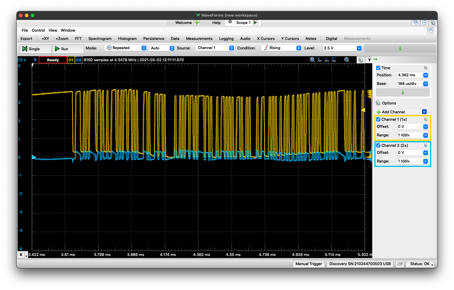 The USB lines on an oscilloscope. Clearly, not the differential pair we’d expect from USB. Yellow is Twine transmit; blue RX.
I fashioned a little custom USB connector so I could connect the USB wires to my USB oscilloscope. After some issues with power supplies, I managed to see data coming off the D+ pin! The shortest pulses look like they’re about 17 µs. If this is actually UART, maybe it’s running at 57600 baud?
Almost! Perhaps I wasn’t actually looking at a short pulse; the true baud rate was 115200 (8N1).
I’m seeing messages! After flipping the Twine over (which triggers an update):
force tcp poll.
nw offset: 0, nwId: 0
Using all channels
Joining nw id: 0
SSID: twine-net
PSK valid: 1
\0NB
Awesome! twine-net is the SSID of my man-in-the-middle WiFi setup. Watching from boot:
\0\0Normal mode
FIRST_BOOT
Zeroing RTC memory
Version: Nov 17 2012 13:47:12.
TID: 00007592f16c0f7f
MAC: 001dc91237dd
boot_req_poll
nw offset: 0, nwId: 0
Using all channels
Joining nw id: 0
SSID: twine-net
PSK valid: 1
\0NB
#

\0NB
do_comm.
Got arm cmd: flip
Entering AP Mode.
Rebooting.
\0%UM\x15Q\0\x8A¥nw offset: 4, nwId: 10
Joining nw id: 10
SSID: \||| Twine
PSK valid: 0
\0NB
nw offset: 4, nwId: 10
Joining nw id: 10
SSID: \||| Twine
PSK valid: 0
\0NB
[... repeats ...]
- SSID
\||| Twineis the setup SSID that broadcast when the device is upside down. - After many repetitions of that message, I flipped Twine back over, and we see the original message about connecting to
twine-net. - The
TIDfield is, I guess, my “Twine ID” – it matches the ID I see on the web management interface.
Ok, this is all making sense. I messed around a bit more and realized that Twine wasn’t actually connecting to my network any more – I think it was some kind of power issue, and the voltage dips a lot (from 5V down to 4.4V) at boot. With a better power supply and a filtering cap, the voltage goes no lower than 4.7V, and Twine is back to connecting:
Connecting... ........Network up.
00007592f16c0f7f
Connecting... ...connected.
Poll...null
len: 2, rep: X
ARM alive!
Disconnect.
In “fast mode” (where Twine just streams data constantly, rather than only when it detects changes), the following messages just repeats. The number after udp is the size of the packet.
do_comm.
Got arm cmd: udp
arm_comm_end.
udp: 347
Occasionally saw a DNS request along the lines of:
Resolving f-router1.0.supermechanical.net...107.21.16.90
Now that the power supply is fixed, I was able to see the proper boot sequence:
\0Normal mode
FIRST_BOOT
Zeroing RTC memory
Version: Nov 17 2012 13:47:12.
TID: 00007592f16c0f7f
MAC: 001dc91237dd
boot_req_poll
nw offset: 0, nwId: 0
Using all channels
Joining nw id: 0
SSID: twine-net
PSK valid: 1
Associated.
Connecting... .........Network up.
TCP poll.
Resolving f-router1.0.supermechanical.net...107.21.16.90
00007592f16c0f7f
Connecting... ...connected.
Poll...null
len: 2, rep: X
ARM alive!
Disconnect.
What about updating a rule? This gives some interesting results.
Poll...arm_flash
Response cmd: start_ack CRC: e78eb697
Syncing with ARM...ARM read timeout
Sync: 79 done.
Reading ARM ID...0420
done.
Erasing ARM...done.
Writing addr: 08000000...done.
Writing addr: 08000100...done.
Writing addr: 08000200...done.
Writing addr: 08000300...done.
Writing addr: 08000400...done.
Writing addr: 08000500...done.
Writing addr: 08000600...done.
Writing addr: 08000700...done.
The writing addr messages continue for a while (up to 0800d800, about 55kB assuming these are byte-aligned addresses). This actually tells us a lot: the main microcontroller on twine is an ARM chip. But we see Erasing ARM... – so clearly that’s not actually where the firmware resides. Additionally, remember that the serial output we’re looking at here comes from the Gainspan WiFi chip. My current understanding of Twine’s operation is:
- Gainspan chip talks to the Twine server.
- ARM MCU interacts with sensors and notifies Gainspan chip when new data is available; Gainspan forwards to server.
- When new rules are available, Gainspan reprograms the MCU.
So this means that – somehow – rules we enter through the web interface are being compiled into an ARM binary and written to the MCU. That doesn’t seem like the safest, or most efficient, workflow, but there’s a lot I don’t know about the backend here.
This data collected over USB also agrees with everythin I saw in the firmware as well as over the packet capture.
My initial assumption:
Presumably the STM32 microcontroller runs the show, the GS1011 provides network connectivity, and either data or firmware are stored in the flash.
was wrong!
Flash Memory Dump
The last investigation I did was sniffing the SPI bus to the external SPI flash memory. The easiest way to do this was to buy an IC Test Clip.
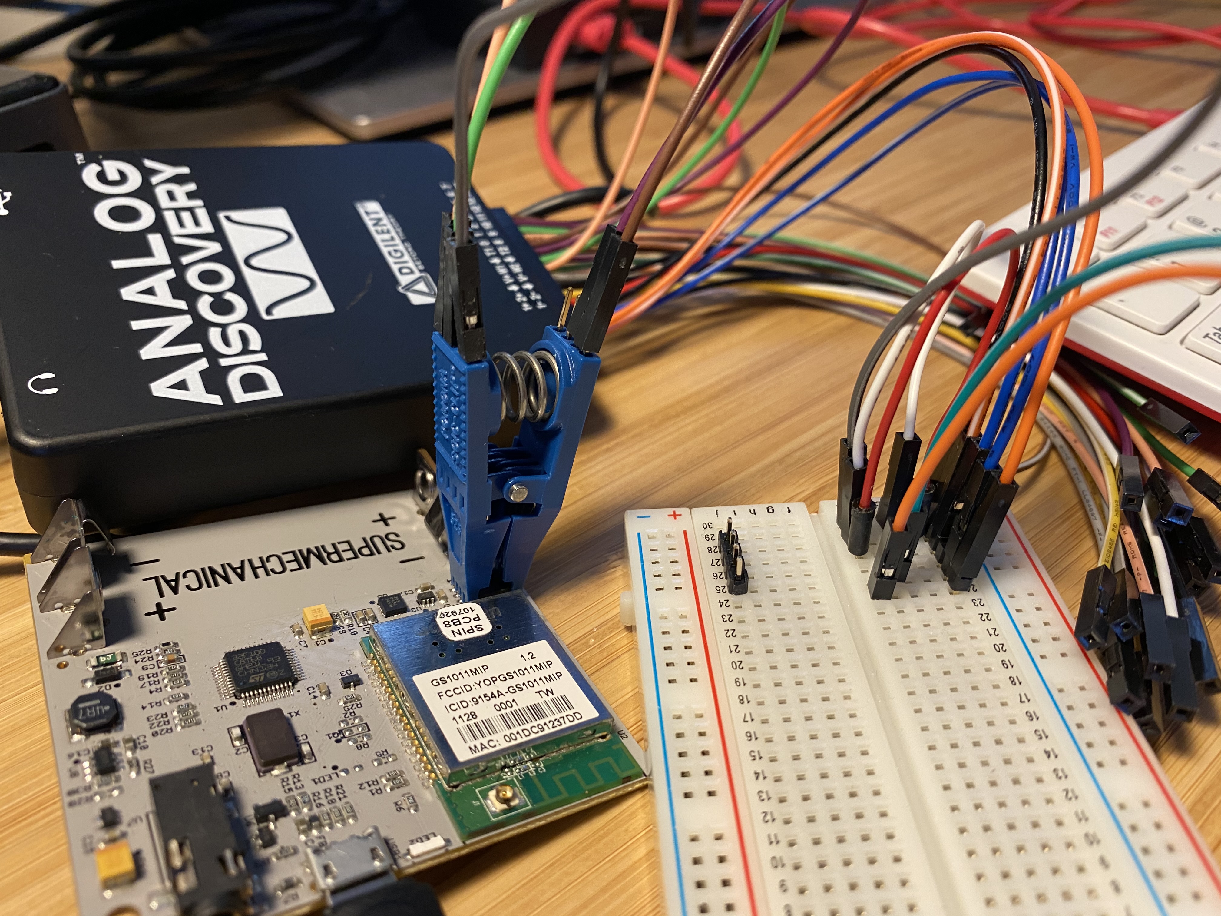 Sniffing the SPI port with a SOIC test clip
I then ran the SPI data into my Analog Discovery logic analyzer:
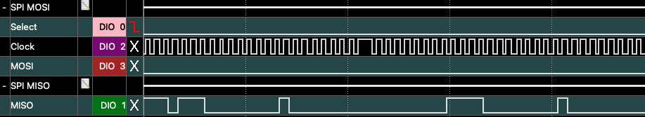 Logic analyzer traces from the SPI bus. In this setup, MISO is from the flash to the Gainspan.
The results were a bit confusing. I saw the following transaction (and variants) occur many times:
Controller | Memory
           |
        05 |        Get Status Reg 1
           | 00     response: 0x00 (no protection, nothing in progress)
        03 |        Read
        07 |
        00 |
        00 |        addr 0x070000
           | 00     response: DATA
           | 01 07 00 16 EE 01 00 00 F0 08 00 BF 83 01 00 00 00 00 00 00 00 00 00 FC FC 00 7B
Sometimes it was at different addresses, but the data contents were always the same. That doesn’t really look like an encryption key to me – lots of null bytes – so maybe it’s some kind of configuration register? Then again, seems like overkill to get a 1 MB flash for just a few dozen bytes.
There was a lot more to investigate with the flash that I never got to, such as:
- What SPI transactions are observed when we perform a rule update?
- Do I ever observe a write?
- Can I dump the entire contents of the chip? (may be difficult in vivo)
to be continued?
Clearly, there are many more mysteries to unravel here, but I think that’s alright: I learned a ton and made some interesting discoveries; my goal wasn’t to reverse engineer this device until there was nothing left.
Over a year later, I think it’s time to call this project finished.