elibaum.com
TOCAR: touch-sensitive digital synthesizer
04 May 2019
This writeup is from Apr 2021, but the project itself took place in the spring of my senior year of college (2019).
For the final project of my Musical Acoustics and Instrument Design class, I wanted to build a digital synth using capacitive touch elements. To keep things simple, this would be a MIDI controller, only; actual sound generation would be handled by my computer (in this case I just used MaxMSP and Garageband).
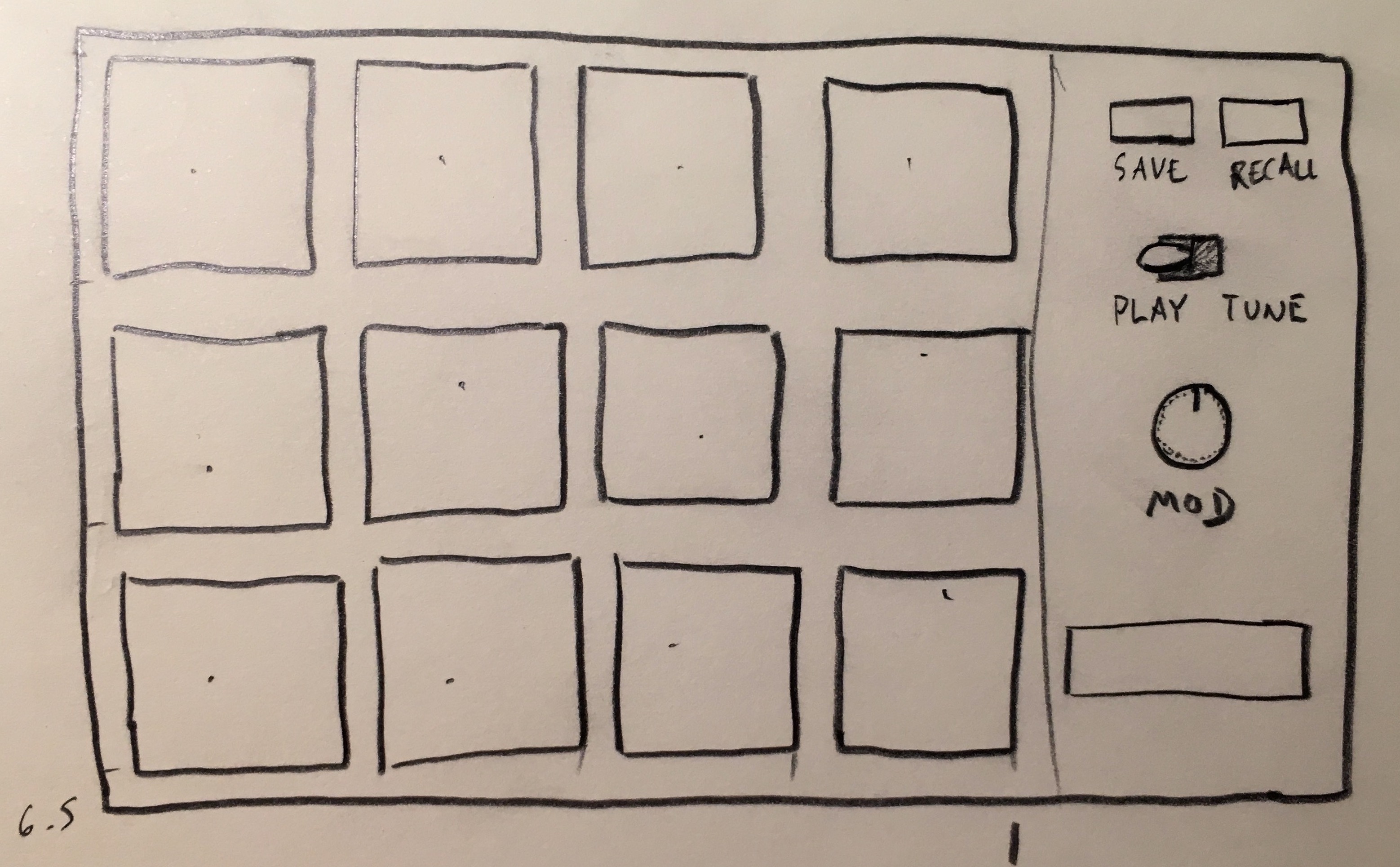 Initial sketch
I wanted each grid element to be individually tunable, so that you could configure the instrument to any set of chords, or arrange the keys for a particular song.
Touch Sensing
To begin, I built a 2x2 prototype, just to figure out the capacitive touch sensing part:
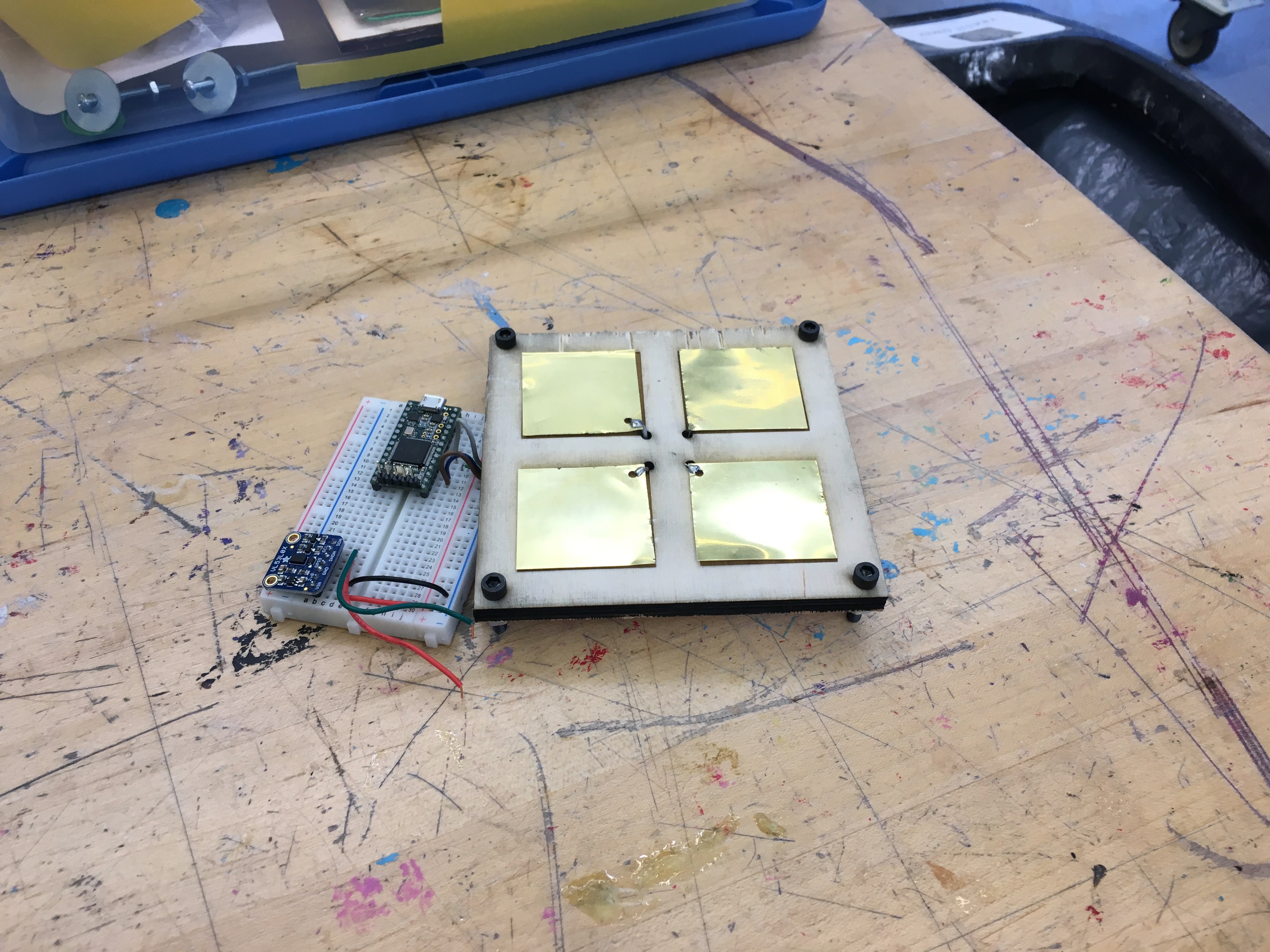 Small prototype
Touch sensing isn’t hard, if you’re just trying to do determine touch vs. no touch. But I wanted to use these metal plates to do either force or distance sensing, as a way of influencing the volume or timbre of the note.
Doing this consistently turned out to be rather tricky: capacitive touch sensors work by measuring the discharge of the capacitor created by a sensing element and the human body. Capacitance is inversely proportional to distance, so I should have been able to just approximate hand distance by inverting the touch sensor measurement. However, there’s a lot more going on. Each plate is forming a complex network of capacitors with the other plates, as well as other electrical components. I even saw differences whether I was powering my calibration setup from my laptop battery or AC.
To test out multiple calibration schemes, I set up a metal pad next to a time-of-flight distance sensor. The TOF sensor served as the measure of actual distance, and I could tune my capacitive touch routines to match.
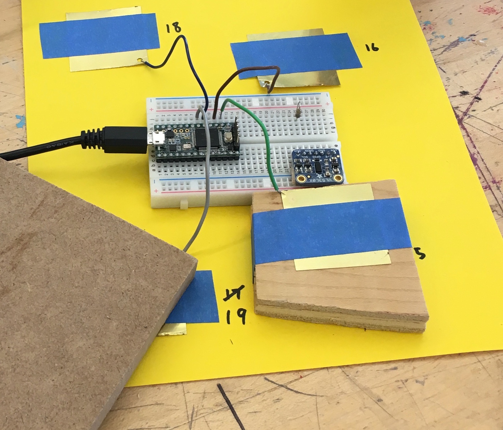 Calibration setup, showing a metal-plate test subject, and the time-of-flight sensor (blue PCB). No, it’s not wireless. I think I took this picture after the fact and didn’t feel like rewiring the setup.
In the following images, the x-axis is the actual distance of my hand, while the y-axis is the (attempted) normalized capacitive-touch value.
I thought some other exponent may work for normalization, but without much luck:
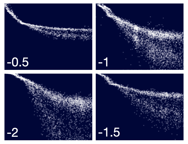 Attempts at normalization with different exponents, i.e.
 1/sqrt(x), 1/x, etc.
Eventually, I realized that I need to normalize the readings with respect to some baseline calibration value. In the final software, I take 100 readings from each of the metal pads at boot, to hopefully cancel at environmental baseline effects.
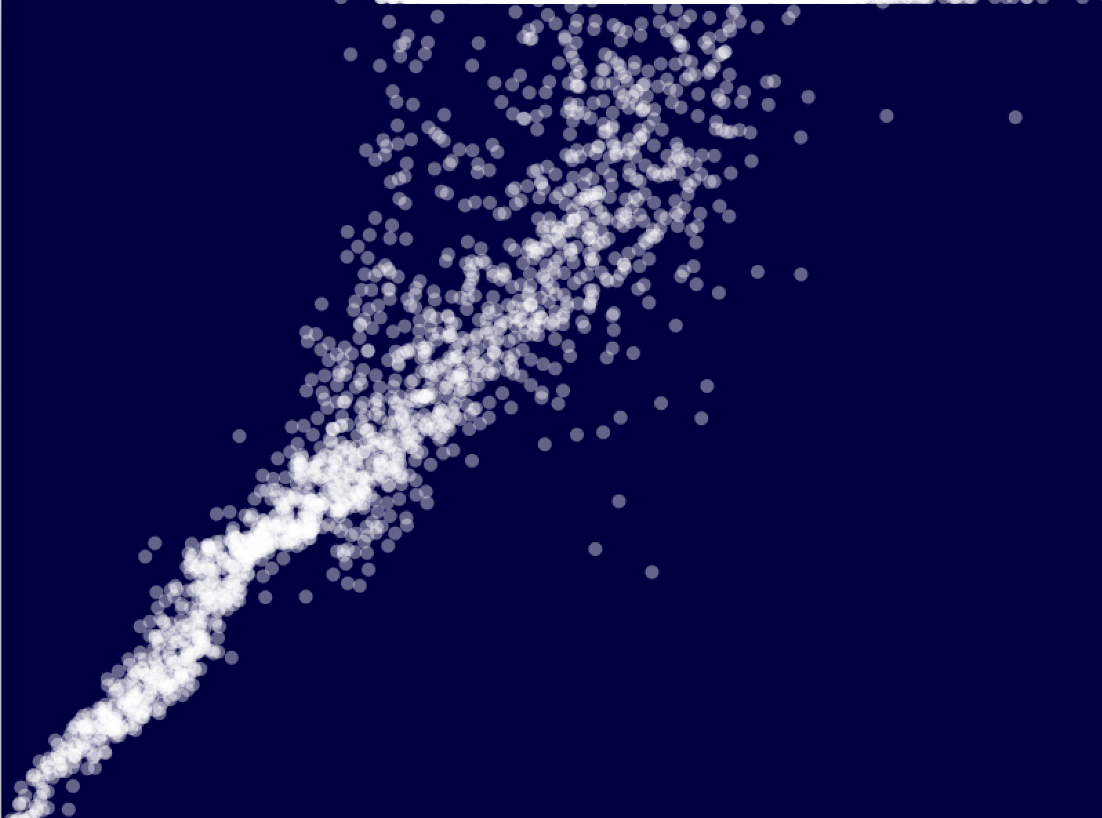 Properly calibrated.
Of course, noise was always going to be a problem at greater distances, but I was mostly concerned with the near-range sensing. A moving average also helped to clean up the signals before converting them into MIDI notes.
Once I moved on from a single sense plate, I ran into some odd coupling issues. Since the signals at play here are so small, the plate wiring itself becomes a part of the capacitor network. I observed behavior where touching one plate would induce signals in adjacent plates (or rather, plates whose wires were touching). To solve this problem, I just had to use shielded cable; the easiest such cable at hand was RCA video cable (the red-yellow-white TV inputs of yesteryear). Then, the only real leakage was at the PCB itself, and between adjacent plates. That interference was minimal enough to not cause problems.
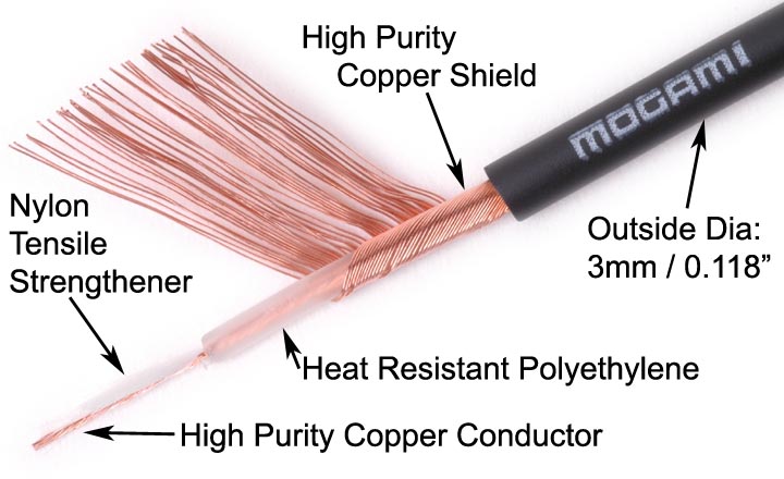 Inside of an RCA cable: signal passed through center, and shield was grounded
Building the prototype
With the touch sensing figured out, I built a larger prototype to start working on the MIDI-controller aspects. The entire system was powered by a Teensy microcontroller, which was particularly well-suited for this project because of its built-in touch sensing hardware.
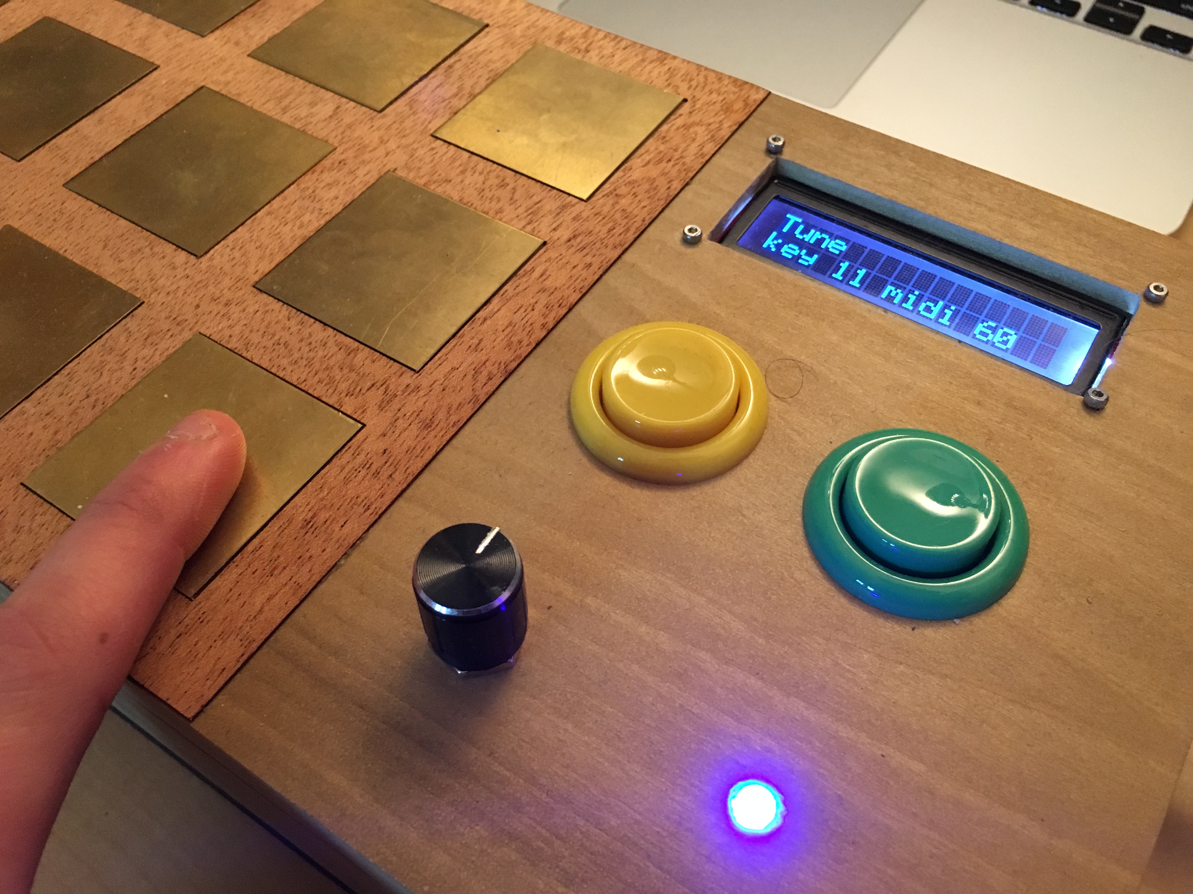
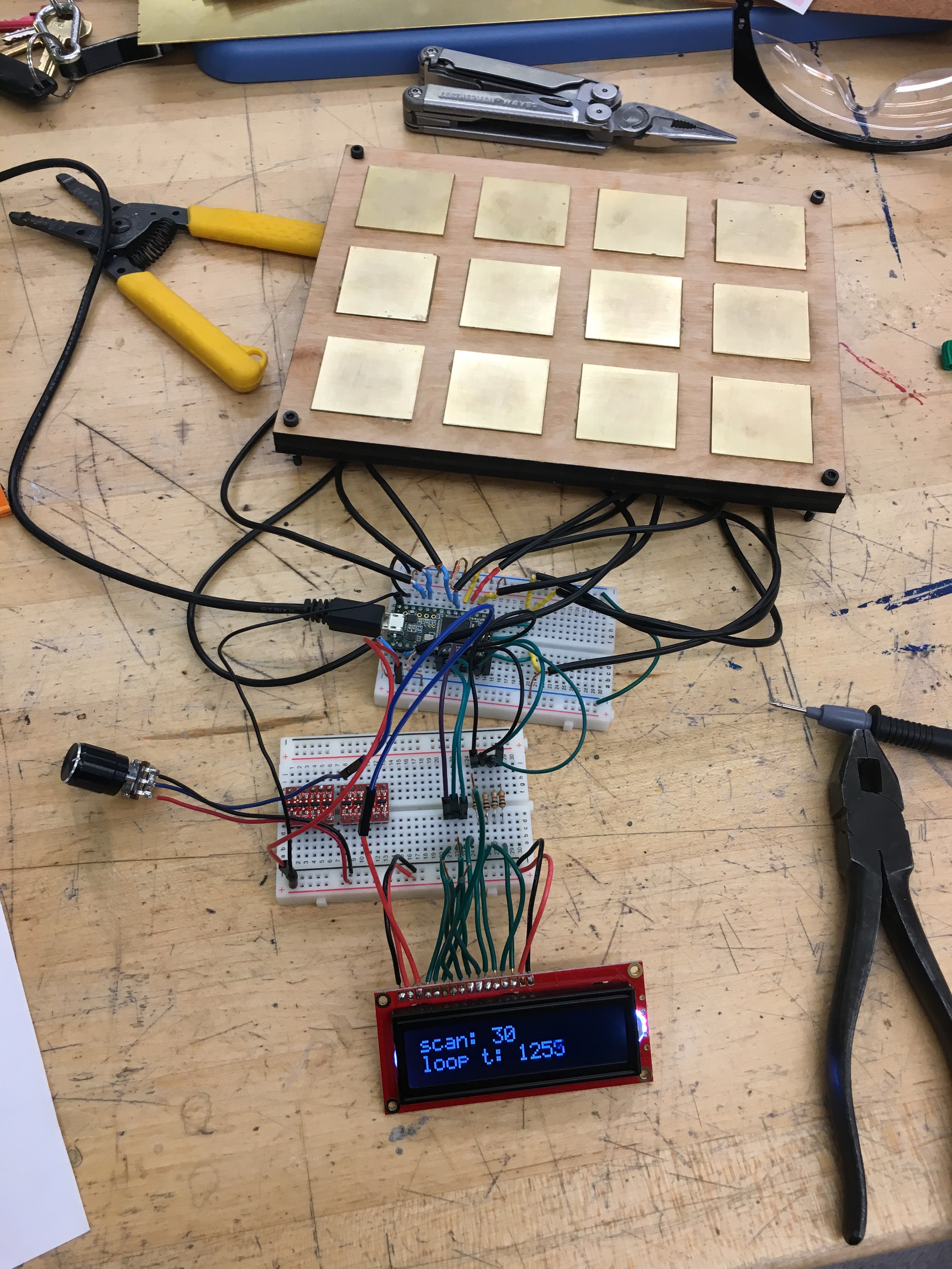 Full prototype: 12 sense pads and an LCD.
I decided to use the touch measurements to determine note velocity - basically how “hard” you press a note. Different MIDI instruments interpret velocity differently (sometimes it just maps to volume; sometimes, like in a piano, it actually loads different samples; and some instruments, like organ, ignore it entirely). After calibration, I was able to figure out distance pretty precisely, so I literally used hand-velocity as the MIDI velocity. If you moved slowly, notes would be quiet and mellow; fast, and they would get loud.
Here’s a demo video of me playing the Garageband Brass Section where you can hear the velocity changes quite clearly:
The real thing
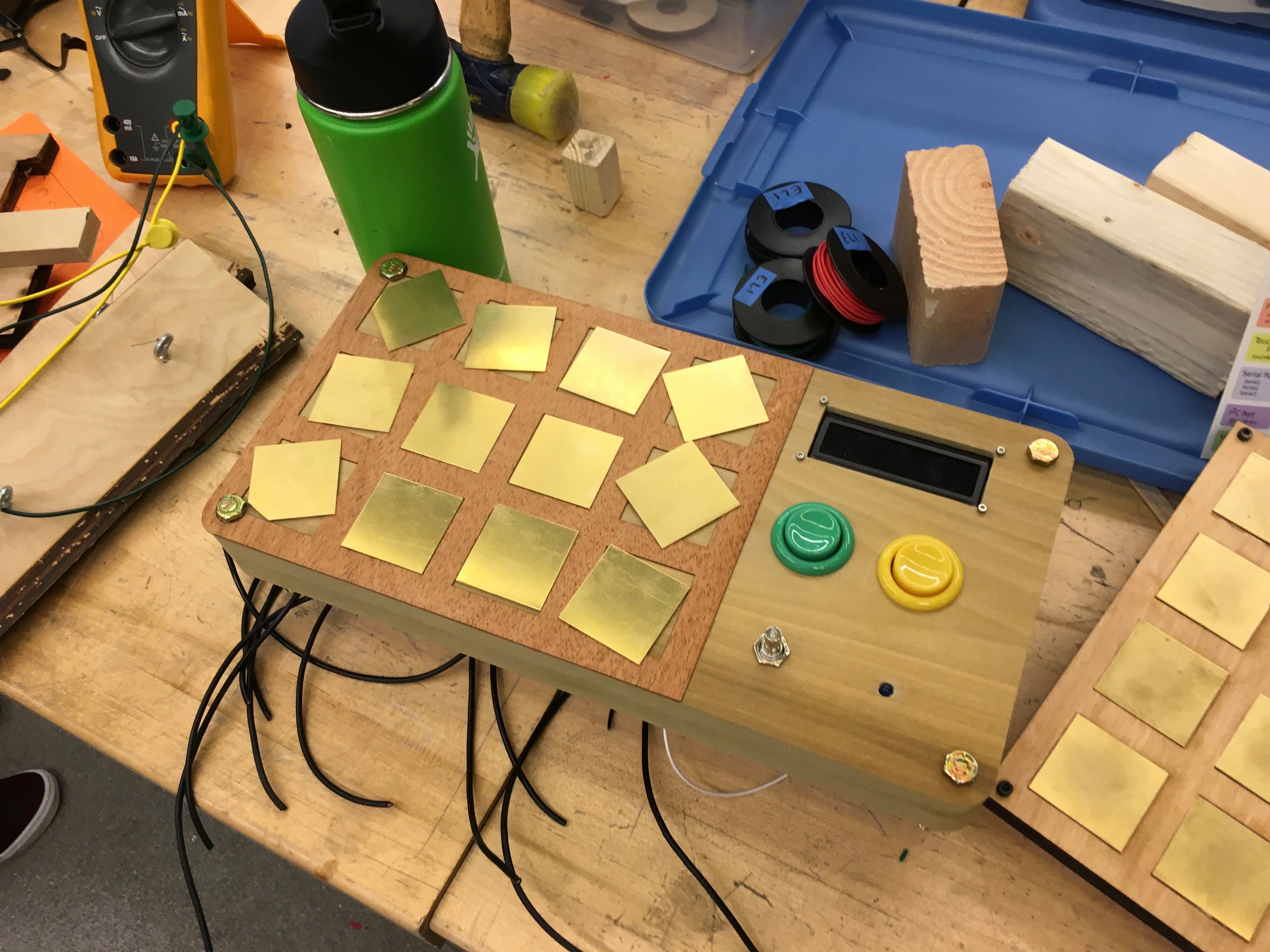
Next, it was on to final assembly. I cut the enclosure in layers. The top layer was the most work - it had holes for wiring, buttons, and the LCD, as well as a veneer cutout to sit around the sense pads. Pictures will explain this better:
 Partial assembly, showing slots for sense plates in the veneer. Black wires are the shielded cables for each plate.
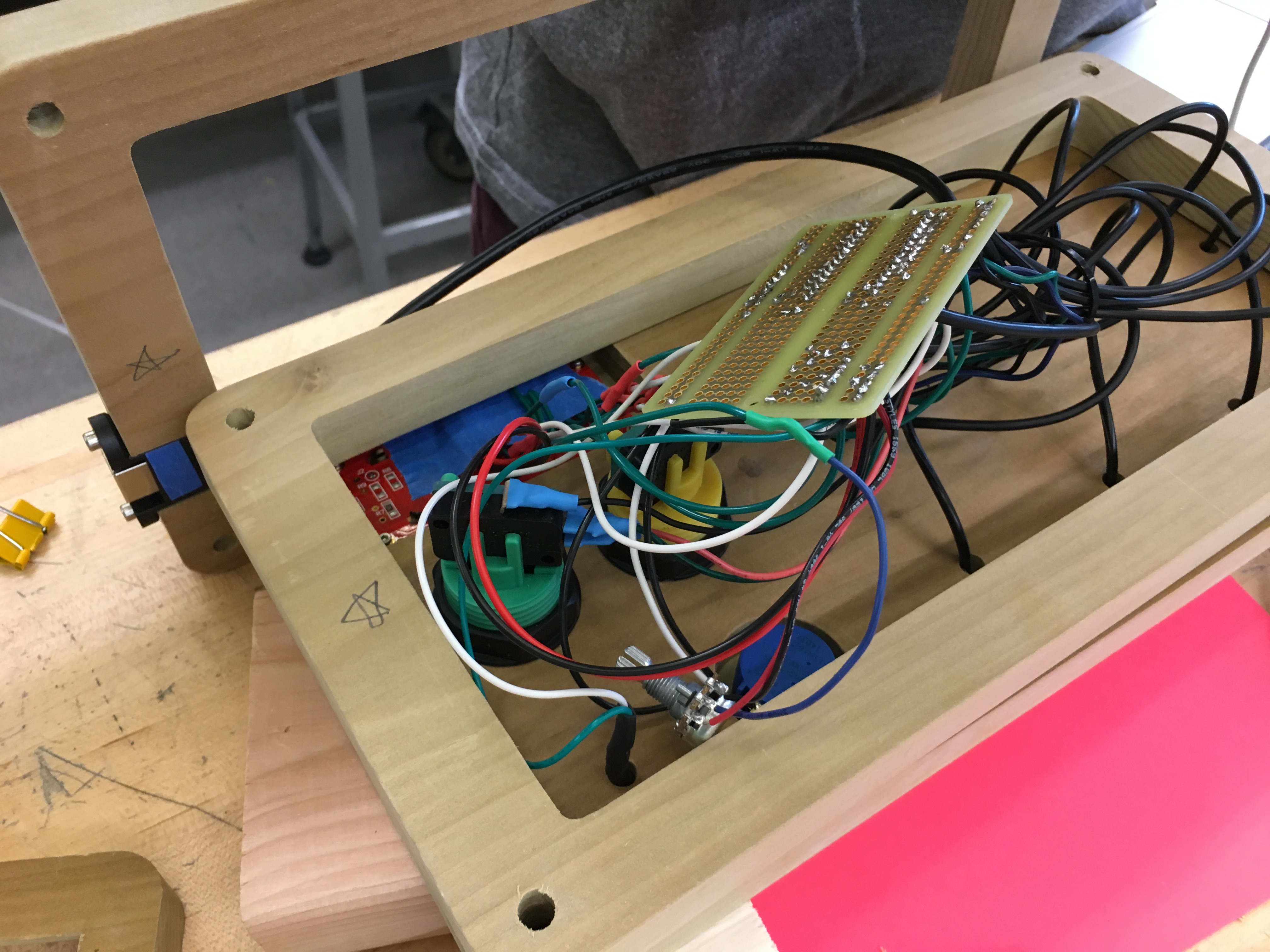 Slightly messy electronics. On the PCB is a Teensy, a couple of pull-up resistors, and a ton of wiring.
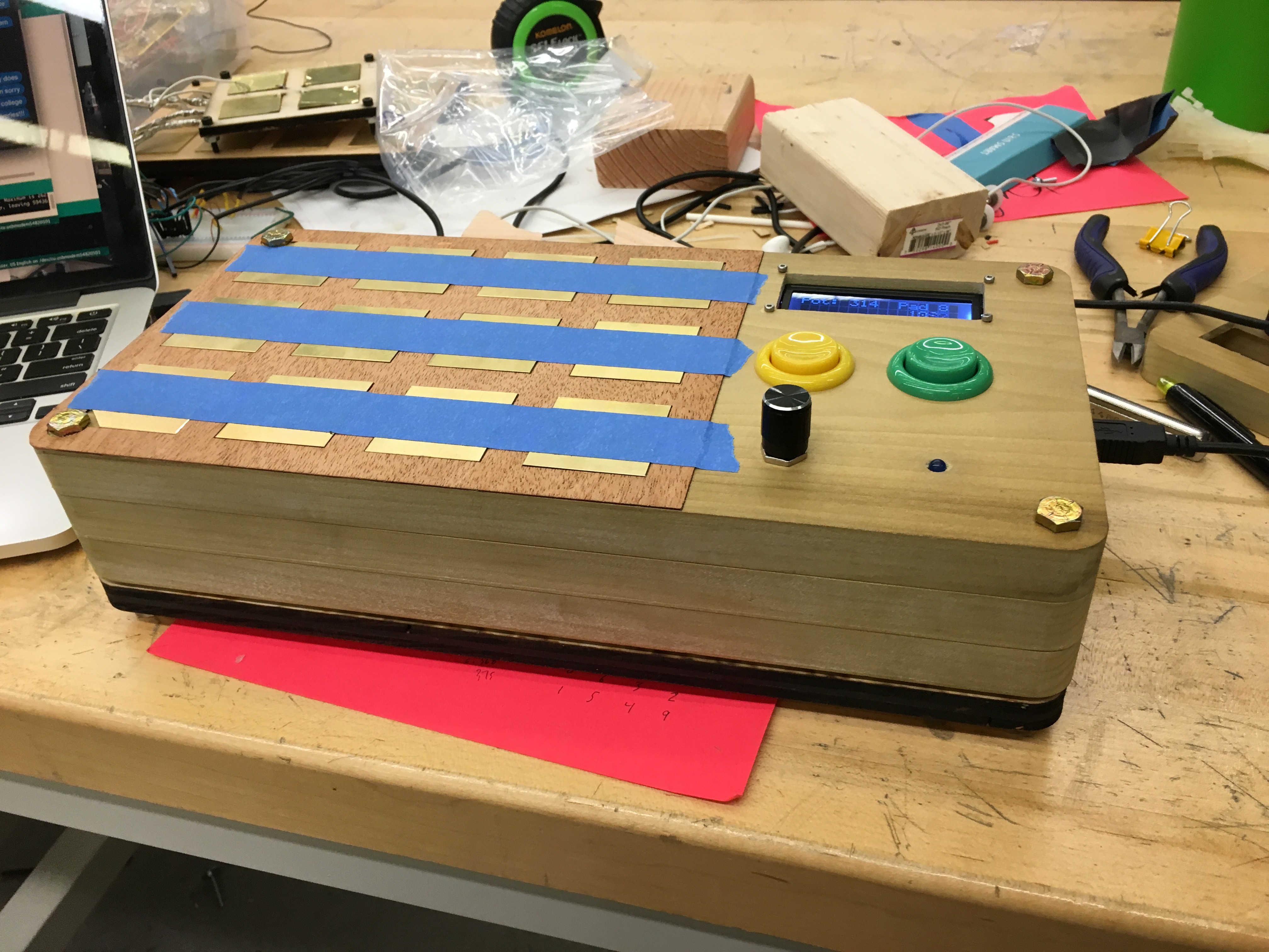 Almost finished! Metal plates taped in place for the glue to dry. Bottom layer was laser cut, hence the darkened ring. The gap between the bottom two layers was due to my failure to properly measure the height of the arcade bottoms - had to add some spacing.
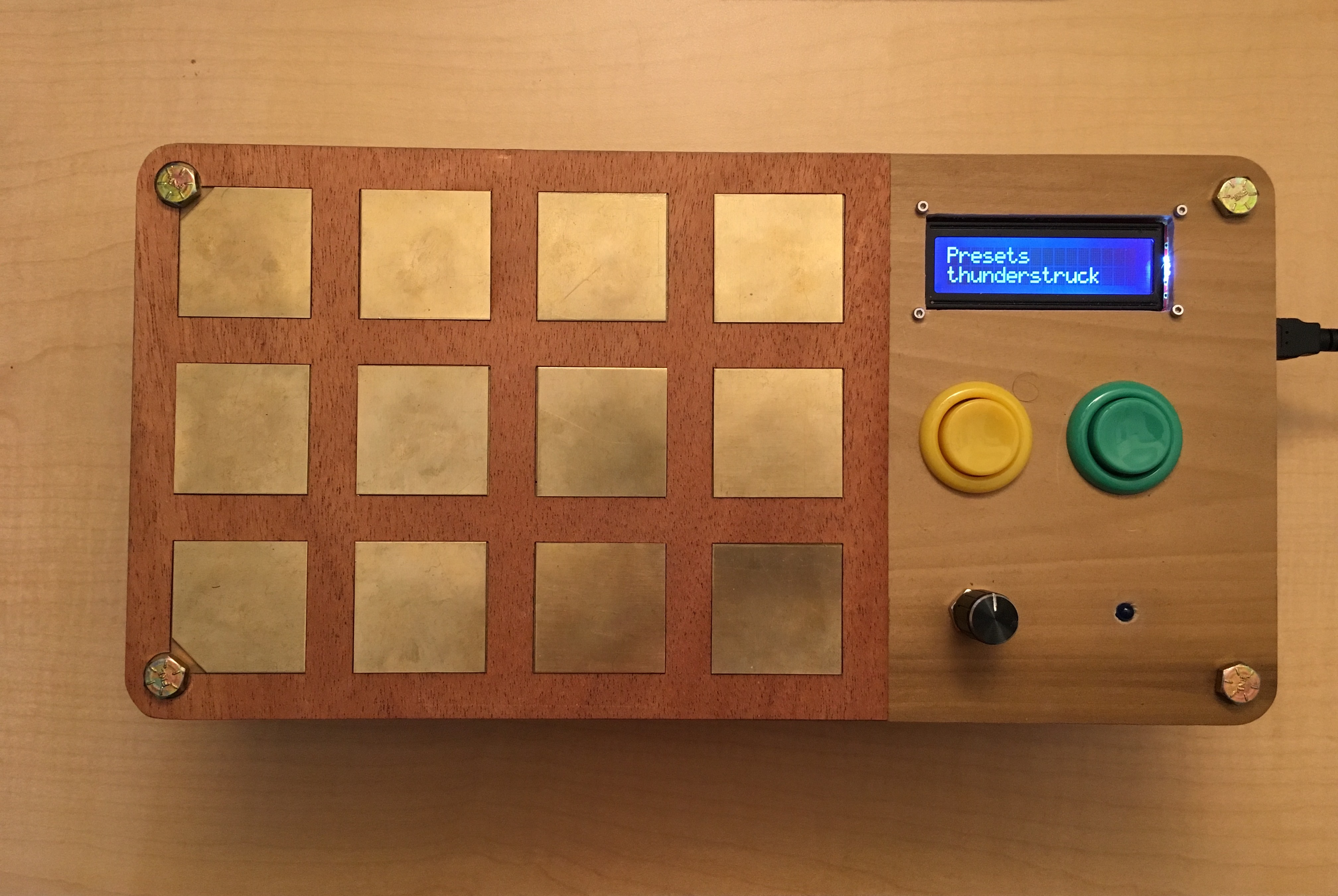 The completed synthesizer!
And finally, my attempt at playing Thunderstruck:
Could use a bit of practice. :)